Description
Modularized Structure/Program & Interface
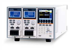
The Instek PEL-2004A is a multiple channel programmable DC Electronic Load with a modularized structure. It is a 4-slot mainframe with a master control unit to hold 4 load modules. When the Instek PEL2004A is configured with 4 load modules rated at 350W each, the PEL-2004A is able to sink up to 1.4kVA of power. This product is designed to meet the test requirements of high-speed semiconductor devices in the market today. The PEL-2000A Series includes two types of mainframes and 4 types of load modules to accommodate users' requirements in a flexible manner. Any load module combination can be used with a mainframe to tailor a test system based on the number of channels, and the maximum load power, voltage and current of each channel. Multiple loads can be connected in parallel to provide a higher-power load to test higher power supply outputs. This flexibility significantly makes the PEL-2004A a very cost-effective instrument for testing a broad range of power supply outputs.
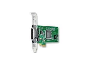
The Instek PEL-2004A supports a total of 12 different programs and 10 sequences to each program for a total of 120 different configurations. For external control and system configuration, the PEL Series has USB and RS-232 interfaces as standard and GPIB as an option. The LabView driver and Data Logging PC software are supported for all the interfaces available. Each channel has an analog control/monitoring connector to externally turn a load on/off and to externally monitor load input, current, and voltage.
Automatic Sequence Function

The Sequence function allows each channel to change load following a pre-defined arbitrary waveform sequence at a selectable speed up to 100?s per step. Further more, every channel can proceed with its respective arbitrary waveform sequence and work together with others under a clock control to provide multi-channel actual-device simulation. This is one of the most powerful features of PEL2004A to simulate the load operations of a multi-output power supply. Under Dynamic mode, the load current or load resistance bounces up and down between two preset levels at a selectable speed up to 25?s per step. This provides standard test procedures for the verification of a power supplys response to very quick load changes. The PEL-2004A provides USB Host/Device and RS-232 interface as standard and GPIB optional for external control and system configuration.
The picture above is an example of a sequence used as a load profile for a single output switching power supply. A load profile is programmed to simulate the current draw of a power supply load. By using a current probe to acquire a current waveform, the PEL-2004A is able to evaluate the performance of a power supply based on the load sequence that is programmed. An oscilloscope is then used to display the result.
Parallel Dynamic Loading

All the load channels in a PEL-2004A mainframe can be connected in parallel to perform any combination of static or dynamic loading. Under Dynamic mode, the load current or load resistance pulses between two preset levels at a predefined speed of up to 25?s per step. When the channels are connected in parallel, dynamic tests are synchronously clocked. The ability to perform parallel dynamic loading gives you the flexibility to perform dynamic tests to high-power power supplies without the need for a dedicated high power electronic load.
Frame Link

The Instek PEL-2004A allows multiple mainframes to be linked together with standard MIL 20-pin connectors to provide higher power load capacity. A maximum of 5 mainframes, including one master and 4 slaves, can be chained together to give a 7kW load capacity for high current and high power applications.
Run Program

Under "Program" mode, up to 12 programs each with 10 panel setup memories, can be edited to create work routines for repetitive tests. After a program has completed, the results of all test steps, including the Go/NoGo judgments will be shown on the screen. Up to 12 programs with a total of up to 120 panel-setup memories can be chained together to be run one after the other.
Specification:
- 4 - slot mainframe with master control unit to hold 4 load modules. (Modules Not Included)
- Mainframe Units require at least 1 Module unit to function
- Sequence function to do high Efficient load simulations
- Flexible configuration with mainframes and plug-in modules
- Multiple independent load inputs up to 8 channels in a mainframe
- Parallel connection of inputs for increased load capacity
- Parallel connection of inputs for static and dynamic tests
- Multiple channels run for dynamic tests under one clock control
- Maximum rated power for low range high resolution CC tests
- Von setting and Von on/off for start-up Von tests
- Program mode to create work routines for repetitive tests
- OPP/OCP/OVP/OTP protections
- External channel control/monitoring via an analog control connector
- Multi-Interface USB Device / Host, RS-232C, and GPIB (Optional)
- Multi-mainframe link up to 5 mainframes in a system


